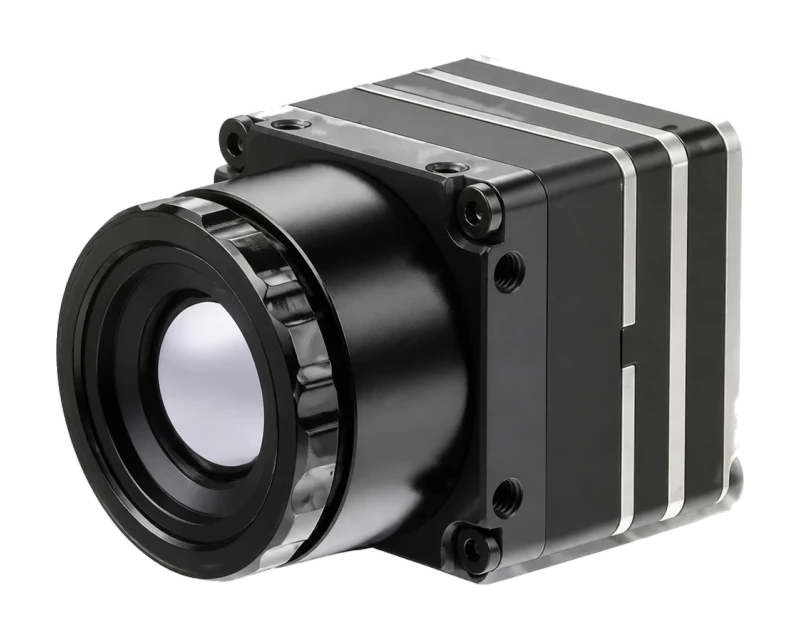
Two measurement ranges
−20°C to 150°C in high-quality mode and 100°C to 650°C in wide-range mode, with typical accuracy of ±2°C or ±2%.
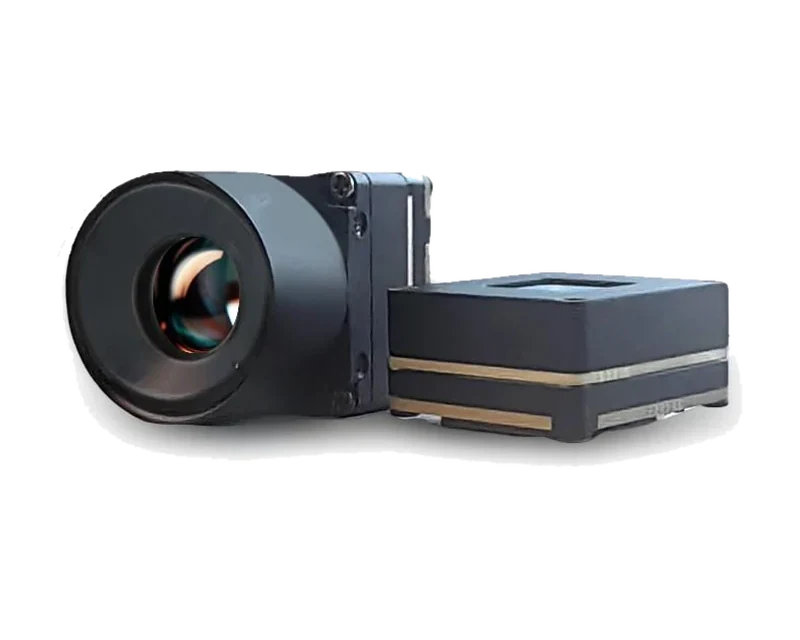
Supplier product photo: the module with its 9.1 mm lens (left) and the 21 × 21 mm core (right).
Thermal imaging module
A 640 × 512 uncooled VOx module with calibrated temperature measurement in two ranges from −20°C to 650°C, typical accuracy of ±2°C or ±2%, and image, temperature data and control over USB Type-C.
No minimum order · In stock · Samples ship within 2–3 working days of payment
Product overview
−20°C to 150°C in high-quality mode and 100°C to 650°C in wide-range mode, with typical accuracy of ±2°C or ±2%.
Thermal image, temperature data and control run over one USB Type-C connection. On a Windows PC it appears as a USB camera, with no driver to install; temperature display and readout are done through TSDK, our SDK for this module.
Shutterless non-uniformity correction is standard. Shutter correction is also listed.
Technical reference
Specifications are supplier document values measured under laboratory conditions.
Request a quote| Parameter | Value |
|---|---|
| Detector & image | |
| Detector | VOx uncooled infrared FPA |
| Resolution | 640 × 512 pixels |
| Pixel pitch | 12 μm |
| Spectral band | 8–14 μm |
| Detector frame rate | 30 Hz |
| NETD | ≤ 40 mK at 25°C, F/1.0, 25 Hz |
| Thermal time constant | < 12 ms |
| Non-uniformity correction | Shutter correction / shutterless algorithm |
| Polarity / palettes | White hot, black hot and pseudo-colour palettes |
| Digital zoom | 1.0–8.0× continuous, 0.1 steps |
| Temperature measurement | |
| Measurement ranges | −20°C to 150°C (high-quality mode); 100°C to 650°C (wide-range mode) |
| Accuracy | ±2°C or ±2% (typical) |
| Ambient temperature for measurement | −10°C to +70°C |
| Lens | |
| Fitted lens | 9.1 mm F1.1, fixed focus |
| Field of view | 48.7° × 38.6° |
| IFOV | 1.3 mrad |
| Lens weight | 10.5 g ±5% |
| Other listed lenses | 13.5 mm F1.0 (31.9° × 25.7°); 18 mm F1.1 (24.2° × 19.5°) |
| Interfaces & power | |
| Interface versions | USB Type-C, MIPI (2-lane) or DVP, all with temperature data |
| Module interfaces | DVP / USB 2.0 / MIPI digital video |
| Communication | UART / I²C / USB 2.0 |
| Power supply | 5 V |
| Typical power consumption | < 0.7 W, USB output at 25°C |
| Mechanical & environment | |
| Core dimensions | 21 × 21 × 10.3 mm, excluding lens |
| Core weight | < 8.6 g, excluding lens |
| Operating temperature | −40°C to +80°C (imaging); −10°C to +70°C (measurement) |
| Storage temperature | −50°C to +85°C |
| Humidity | 5%–95%, non-condensing |
| Vibration | 6.06 g random, all axes |
| Shock | 80 g, 4 ms, saw-tooth, 3 axes, 6 directions |
Interface definition
The core uses a 50-pin Hirose DF40 board-to-board connector (DF40C-50DP-0.4V). The USB version ships with a USB Type-C board.
For selection only. If you need hardware development documents, tell us and we will check with the manufacturer.
| Pins | Signal | Function |
|---|---|---|
| 1, 50 | VDD5.0 | Power input; the module runs from a single 5 V supply |
| 3, 48 | VDD3.3 | Reserved; no supply needed |
| 2, 4, 7, 10, 21, 25, 26, 30, 41, 44, 47, 49 | DGND | Ground |
| 14, 15 | USB_DP, USB_DM | USB 2.0 data |
| 8, 9 | — | Not used on this model |
| 12, 13, 40, 39, 38, 37 | MIPI_CK_P/N, MIPI_D0_P/N, MIPI_D1_P/N | 2-lane MIPI output |
| 20, 33, 19, 32, 11, 18, 34, 17, 35, 16, 36 | DVP_CLK, DVP_VSYNC, DVP_HSYNC, DVP_DATA15–8 | DVP video output; DATA15 is the MSB, 1.8 V by default (3.3 V by command) |
| 43, 42 | UART0_TX, UART0_RX | Control UART, 3.3 V |
| 24, 27 | UART1_TX, UART1_RX | Debug UART or general I/O, 3.3 V |
| 22, 29 | I2C_SLV_SCK, I2C_SLV_SDA | I²C slave, 1.8 V by default (3.3 V by command) |
| 6, 45 | IIC_MST1_SCK, IIC_MST1_SDA | I²C master, 3.3 V |
| 23 | DVP_FSYNC | External sync input, or general I/O |
| 28 | WORK_MODE | Pull high for update mode; leave unconnected otherwise |
| 31 | Nrst | Pull low to reset; leave unconnected otherwise |
| 5, 46 | NC | Not for use |
ENGINEERING & PROCUREMENT
MINI 640-2 is an observation module: a 60 Hz detector, CVBS and USB 2.0 video, and no calibrated temperature output. MINI 640-2 Radiometric adds calibrated temperature measurement: two measurement ranges, typical accuracy of ±2°C or ±2%, and temperature data over USB Type-C. Both use a 640 × 512, 12 μm VOx detector in the 21 × 21 mm format.
A non-radiometric module shows relative heat differences as an image. A radiometric module is calibrated to output temperature values, so you can read the temperature of a spot or area. MINI 640-2 is non-radiometric; MINI 640-2 Radiometric outputs temperature data over USB with typical accuracy of ±2°C or ±2%.
The manual lists −20°C to 150°C in high-quality mode and 100°C to 650°C in wide-range mode, with typical accuracy of ±2°C or ±2%. Temperature measurement is specified at an ambient temperature of −10°C to +70°C; imaging works from −40°C to +80°C.
Yes. Thermal image, temperature data and control run over one USB Type-C cable. Plug the module into a Windows PC and you see the thermal picture: Windows sees it as a USB camera, with no driver to install; on a laptop with a built-in webcam, disable the built-in camera first. Temperature display and readout are done through TSDK, our SDK for this module, with versions for Linux (Ubuntu, Raspberry Pi, Jetson). TSDK has been tested on our modules and comes at no extra charge. If you need it, tell us: we provide it after payment is confirmed, before the module ships. Tell us your host platform when you request a quotation.
Full-frame temperature data or spot readings (maximum, minimum and center), depending on your application. Tell us which you need when you request a quotation.
The in-stock sample uses a 9.1 mm F1.1 lens (48.7° × 38.6°). The supplier manual also lists 13.5 mm F1.0 (31.9° × 25.7°) and 18 mm F1.1 (24.2° × 19.5°) lenses for the 640 × 512 version. Both are non-standard lenses: samples ship within 15 working days of payment, and prices are confirmed in your quotation.
Yes. The same radiometric core comes in 384 × 288 (30 Hz) and 256 × 192 (25 Hz) versions with the same 21 × 21 mm format, measurement ranges, typical accuracy and interfaces. Both are supplied with a 4 mm F1.1 lens: 64.1° × 48.8° on the 384 version and 45.5° × 33.5° on the 256 version. Samples are in stock and ship within 2–3 working days of payment.
The module with its 9.1 mm F1.1 lens, the USB Type-C board and a USB 2.0 cable. If you need TSDK, it is provided separately after payment is confirmed, at no extra charge. If you plan to design your own host board, tell us which documents you need and we will check with the manufacturer.
The core uses a 50-pin Hirose DF40 board-to-board connector (DF40C-50DP-0.4V), with a single 5 V supply. The pin table on this page is for selection only; if you need hardware development documents, tell us and we will check with the manufacturer.
There is no minimum order; you can start with one unit. MINI 640-2 Radiometric is in stock, and samples ship within 2–3 working days of payment. Prices are quoted for your configuration, quantity and destination.
Prepare the next step
Tell us the application, lens, output and quantity. We confirm the sample configuration and price before you order.
DESIGN-IN GUIDES
Choose a lens for a 640 × 512 thermal core: coverage width, pixel size and measuring distance for 9.1, 13.5 and 18 mm lenses, and the horizontal-or-diagonal check for wide angles.
How temperature data leaves a radiometric thermal core over USB, MIPI CSI-2 or DVP, why analog video cannot carry it, and five questions to ask before design-in.
A mechanical checklist for a 21 × 21 mm thermal core: size with the lens, M2 mounting, the 50-pin DF40 connector, 5 V power, the infrared window, heat and ambient limits.
What a radiometric module’s “±2°C or ±2%” accuracy covers, and what matters more on a real target: emissivity, reflections, spot size, distance, windows, ambient temperature and NUC.
Why a thermal core smears on drones, vehicles and trains, why a higher frame rate does not fix it, and at what speed temperature readings drop (calculated).
Why glass and most plastics block long-wave infrared, what a germanium window and its coatings need, how a window shifts readings, and how to size it.
What thermal payloads on inspection robots use, and what to check: pixels on target, field of view in aisles, temperature range, stop-and-measure, close focus.
Product documents
Start with the product overview. Ask us for the technical documents available for your selected configuration.
English PDF · 2026 edition
Thermal imaging module · Parameter sheet · On request
Purchasing support
We clarify your product and application requirements, then coordinate supplier confirmation of the proposed configuration.
We record the agreed sample model, configuration and included items, then review any changes before an order proceeds.
We track supplier progress, coordinate order documents and follow up on open issues, keeping the next step and responsible party clear.
Continue exploring
A compact core for thermal observation.